Sunday, July 15, 2012

One of the other projects I've been working on is a garden watering timer, the house we bought has a James Hardie system that wasn't working, so I salvaged the (3)valves out of the ground, (the gardens had been redone and the sprinkler ends removed earlier) the control box off the wall, just for the 24v transformer inside it.
A coupla weeks ago I bought a Leostick (http://www.freetronics.com/products/leostick) from the local Jaycar (there is 3 Jaycars equal distance from our home).
I had found a Menu library written to help with devolopment. Link(http://www.coagula.org/content/sites/default/files/source/menu_and_lcd_display.pde)
and adjusted it for my project.


    Menu Structure
    M_Menu.VV
    RLed.VV>>                               BLed.VV>>                                   GLed.VV
    Rled On.VV>>RLed Off            Bled On.VV>>BLed Off                 Gled On.VV>>GLed Off
    Man>>Timer.VV                        Man>>Timer.VV                            Man>>Timer.VV
    5mins>>10 mins>>15 mins>>20 mins      
    **Note** Manual time runs for 30 mins then turns off


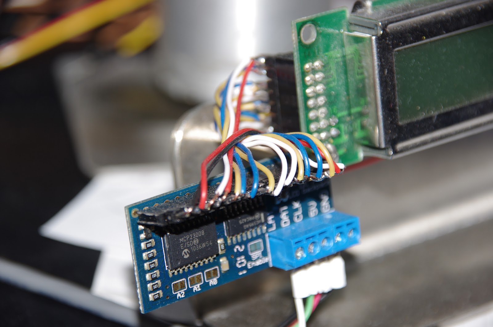
in the photo i using a 16x2 LCD at D7, D6, D5, D4, D3, D2, 3 momentary push buttons at D8, D11, D12, potentiometer for contrast and the the leostick, which has a RGB LED  at D9, D10, D13.
so on my to do list was to add a real time clock and connect relays, put it all in a box and set up the pipes / sprinklers.
so yesterday i got a RTC (http://www.freetronics.com/collections/modules/products/real-time-clock-rtc-moduleand 4 channel relay board (http://www.freetronics.com/pages/relay4-4-channel-relay-driver-module-quickstart-guide).
i spent all yesterday trying to get the RTC to work for me, but the library's i found didn't function correctly for me.
Tada the RTC finally works for me turns out the Serial baud rate was set wrong on the test program so when i ran in all got was jiberish, until until i set the baud rate correctly and shows the correct values, now i can move forward.
so the Library / Code i used is from here
 http://soiling-detector.googlecode.com/files/DS3231updated.zip
link found here http://arduino.cc/forum/index.php/topic,57642.0.html.
to set the time / date the format used somewhat gathered from the sketch and the .cpp or .h files
is YYMMDDwHHMMSS , the 'w' is the day of week number 1-7 and i guessing 1=sun 2=mon but don't quote me on that, and put an x at the end as explained in the sketch.
now to make the RTC work with the leostick and the lcd display.


Sunday, July 8, 2012

tried to work out the angles on the arm today but i've given up again for the time being..the IK code doesn't drive the arm out straight, so i cut and pasted the code to a new sketch but just to control each servo separately, to make sure the servos are working correctly. then i had a break to do some work on the deck,
ended up buying a ton of stuff from bunnings,.borrowed the drum sander from work to clean off the old paint, cleaned about 10 boards (which worked a treat), replaced 1 that was sticking up from the join in the runners underneath, which required chiselling out to level up. should look good when done. about of the short of my day today.

Saturday, July 7, 2012

robot arm

so for a while i have dreaming (or thought) about building a robot arm.
to start of with this project i bought a arduino uno SIK for my birthday..
it's pretty cool as there is tons of information on the net.
anyway there are some others who have converted robot arms or or bought kits but, for me that's not fun,
besides i'm more a mechanical sort of person than electrical.
for my robot arm i've used R/C servo motors (4) aluminium frame for lightness including the holes for weight reduction. and counter weight helps with the overall balance.

i had the arm working then left it for a while and pulled it apart and changed it for a camera pan but, not as exciting for me.

it produces a series of photos, which i stitched together with Huggin (http://hugin.sourceforge.net/)
huggin works best with less photo's (not 26 like i tried).
anyway i digress, so today i put it back together to try some adjustments i made to the IK code.
i use a Wii nunchuck to control the arm. a 40 x 2 character LCD with a i2c lcd backpack i purchased from  Adafruit, it was designed for 16,2 lcd's with the connecter on the top or bottom but, as the lcd i have has the connector at the end  

i fitted a homemade adapted cable to make it work with my 40,2.
looks like the adjustments i've made for the IK are not working and more tweaking is required
the trigonometry can be a pain to get right.. i'll get to it later.